13215150267
热门关键词: 光伏太阳能板天窗 防水光伏太阳能电池板 U玻璃光伏太阳能电池板


组件的接地,如果条件允许,可以单独引一根地线,如果条件不允许,也可以和建筑物内防雷带接在一起。逆变器一般有两个接地点,机壳接地点和输出接线端子接地点,机壳接地点一般是安全接地,可以和组件系统的接地点接在一起,但不要和组件直接接在一起,最好直接和和埋在地下的接地带连接,如果条件不允许,也可以和建筑物内防雷带接在一起。输出接线端子接地点,是工作接地,要和输出电源端的地线接在一起。
After the installation of the photovoltaic system, sometimes some strange problems will occur, such as frequently reporting the ground leakage current and insulation resistance fault, but there is no fault during the detection; Sometimes the power grid
voltage fault is reported, and the voltage display is inaccurate; When the inverter works in cloudy and rainy days, household appliances will be charged; When the inverter works in thunderstorm days, sometimes the inverter will be damaged by lightning.
In case of these problems, the photovoltaic grounding device may have problems.
01. Role of photovoltaic system grounding
In the installation of photovoltaic system, the module needs to be grounded,
and the inverter also needs to be grounded. What is the purpose of the grounding of the module and the inverter?
The grounding device of photovoltaic system is divided into working grounding and safety grounding. The main function
of component grounding is lightning protection grounding. Lightning protection grounding leads lightning to the earth to prevent lightning current from causing electric shock to people or damage to property. The main parts of the photovoltaic power generation
system are installed in the open air, and the distribution area is large, so there are direct and indirect lightning hazards. At the same time, the photovoltaic power generation system is directly connected with the relevant electrical equipment and buildings.
If the photovoltaic module is struck by lightning, it will also involve the electrical loads in the relevant equipment and buildings. In order to avoid the damage of lightning to photovoltaic power generation system, it is necessary to set lightning protection
grounding system for protection.
Inverter grounding includes lightning protection grounding and working grounding. The functions of safety grounding and components are the same. There are three types of working grounding:
1. Inverter reference potential
The earth is often used as a reference ground in electrical systems. The voltage on the grid side also regards the earth as zero potential. With the ground as the zero potential, the
AC voltage and DC voltage of the inverter can be detected more accurately and stably. The ground should also be used as a reference point for detecting the leakage current of the components to the ground.
2. Shielding grounding
against electromagnetic interference
Inverter is a device that converts direct current into alternating current. It has power electronic conversion. The frequency is generally 5-30khz. Therefore, it will generate alternating electric
field, so it will also generate electromagnetic radiation. External electromagnetic interference will also affect the operation of the inverter. The electrical interference source will be introduced to the earth to suppress the impact of external electromagnetic
interference on the inverter, and also reduce the impact of interference generated by the inverter on other electronic equipment.
3. Anti component PID
PID (potentialinduceddegradation) effect is called potential
induced attenuation. The direct harm of PID is that a large number of charges gather on the surface of the battery, making the battery surface passivated. The harm of PID effect makes the power of the battery module decay sharply. Reduce the output power
of the solar power station, reduce the power generation, and reduce the power station income of the solar power station. The grounding system can delay the attenuation process of components.
02. Grounding specification of photovoltaic
system
Photovoltaic system requires a good grounding system, which is not only the need for stable and reliable operation of equipment, but also the need to ensure equipment and personal safety. The photovoltaic grounding system
includes lightning protection ground, safety ground and working ground. The three grounding wires are connected together at a common point and then connected to the grounding body through equipotential bonding belt. In addition to having a good grounding
body, the length and material specification of the grounding wire are extremely important for a good grounding system.
Length requirements: in order to prevent damage to equipment caused by high potential generated by lightning
current or fault current, the length of grounding wire shall be as short as possible, and bending and winding shall be avoided as much as possible. Generally, the length of grounding branch line shall be less than 15m.
Material
specification: the photovoltaic standard has clear provisions for grounding wire. The grounding wire is related to the area of AC phase line or DC line. When the sectional area of phase line is less than 2.5 square meters; When the cross-sectional area
of phase line is less than 16 square meters, the minimum cross-sectional area of ground wire is 35 square meters, and the cross-sectional area of ground wire is half of the cross-sectional area of phase line.
Grounding types and
requirements include the following aspects. First, lightning protection and grounding: including lightning rod (strip), down lead, grounding body, etc., the grounding resistance is required to be less than 10 ohms, and it is best to consider setting the
grounding body separately; Second, safety protection grounding, working grounding, shielding grounding, etc. the grounding resistance is required to be less than or equal to 4 ohms. When safety protection grounding, working grounding, shielding grounding
and lightning protection grounding share a set of grounding devices, the grounding resistance shall be determined according to the minimum value of 4 ohms; If the lightning protection has been provided with a separate grounding device, the other three
grounding devices should share a set of grounding devices, and the grounding resistance should not be greater than the minimum value.
03. Measurement method for grounding of photovoltaic system
After the grounding
system is completed, it is very important to correctly measure the grounding resistance. However, the grounding resistance is a little different from our common resistance components. It can not be measured with an ordinary multimeter, so special instruments
must be used. There are usually the following measurement methods: two-wire method, three wire method, four wire method, single clamp method and double clamp method. Each has its own characteristics. In the actual measurement, try to select the correct
way to make the measurement results accurate.
(1) Voltage method
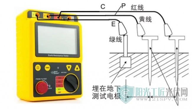
The two-wire method, three wire method and four wire method are all voltage methods. The specific principle is shown in the figure below. Apply
an AC current I to the ground electrode C and electrode e, and then measure the potential difference V between point E and point P. the ground resistance R is equal to v/i.
Note: there must be two grounding rods: an
auxiliary ground and a detection electrode. The distance between each grounding electrode shall not be less than 20 meters. The grounding electrode shall be laid to about 1.5 meters deep in a row. The soil shall be wet. If it is dry land, or stone or
sand, it shall be tested with enough water.
The four wire method is basically the same as the three wire method. It replaces the three wire method when measuring the low ground resistance and eliminating the influence of the measured
cable resistance on the measurement results. Four electrodes of small size are inserted into the ground at the same depth and the same distance (straight line) and measured. This method has the highest accuracy among all the grounding resistance measurement
methods.
(2) Current method
Both the single clamp method and the double clamp method are current methods, which can measure the resistance without disconnecting the ground system. It is fast, simple
and reliable without disconnecting the lead wire and auxiliary electrode, and also includes the grounding and overall grounding connection resistance in measurement.
The basic principle of the clamp type grounding resistance tester
is to measure the loop resistance. The jaw part of the clamp meter is composed of a voltage coil and a current coil. The voltage coil provides an excitation signal and induces an electric potential E on the measured circuit. Under the action of potential
E, current I will be generated in the measured circuit. Clamp the meter to measure E and I, and then the measured resistance r=e/i can be obtained.
(3) Single clamp method
Measure the grounding resistance
of each grounding point in the multi-point grounding, and do not disconnect the grounding connection to prevent danger. It is applicable to multi-point grounding without disconnecting the connection. Measure the resistance of each grounding point. The
method is to use current clamp to monitor the current on the measured grounding point.
(4) Double clamp method
Multi point grounding, no auxiliary ground pile, single grounding measurement. The method is to
connect the current clamp to the corresponding socket, clamp the two clamps on the grounding conductor, and the distance between the two clamps should be greater than 0.25m.
Precautions for grounding of photovoltaic system
In principle, the safety grounding and working grounding should not be connected together as much as possible, because the safety grounding does not work often, but the current is large and the voltage is relatively high; The working grounding
current is that the equipment operates when it is working and is connected with the weak current part of the inverter PCB. The current is very small and the voltage is also very low. If connected together, interference may occur.
For the grounding of components, if conditions permit, a ground wire can be led separately. If conditions do not permit, it can also be connected with the lightning protection belt in the building. The inverter generally has two grounding points, the
chassis grounding point and the output terminal grounding point. The chassis grounding point is generally a safety grounding, which can be connected with the component system grounding point, but not directly with the component. It is better to be directly
connected with the buried grounding strip. If conditions do not permit, it can also be connected with the lightning protection strip in the building. The output terminal grounding point is the working grounding, which shall be connected with the ground
wire at the output power terminal.